Chapter 11 — Installation and Debugging
This chapter provides step-by-step guidance for the physical installation of surface water monitoring stations, including civil works, mechanical mounting, electrical wiring, sensor deployment, and system commissioning. It also covers the debugging procedures required to verify correct operation before handover, and the documentation that must be completed at each stage.
11.1 Installation Requirements
The installation of a surface water monitoring station involves coordinated work across civil, mechanical, electrical, and communications disciplines. The photograph below shows a typical riverbank installation in progress, with a technician mounting the sensor bracket to a concrete pier while the IP68 multiparameter sonde is prepared for deployment. The weatherproof cabinet with solar panel and 4G antenna is visible in the background.
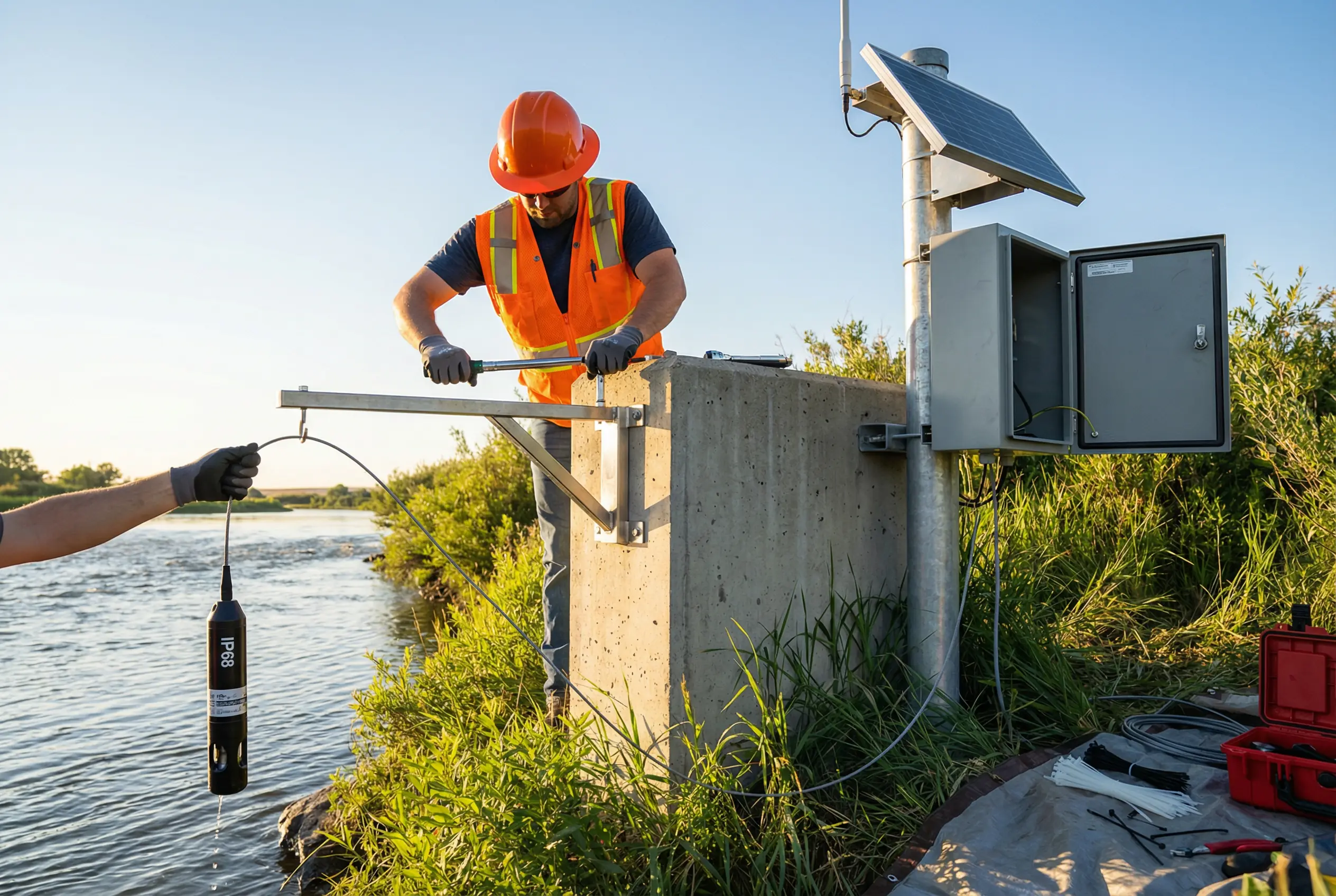
Figure 11.1: Installation requirements — field installation of surface water monitoring station on concrete riverbank pier, showing sensor bracket mounting, IP68 sonde deployment, weatherproof cabinet with solar panel and 4G antenna, and professional safety equipment (hard hat, safety vest, gloves)
11.2 Cabinet Wiring and Commissioning
The cabinet wiring and commissioning phase involves connecting all field cables to the terminal blocks, configuring the RTU and gateway devices, and verifying data flow from sensors to the cloud platform. The photograph below shows a technician performing the final wiring connections inside the monitoring cabinet, with a laptop displaying live data from the cloud platform.
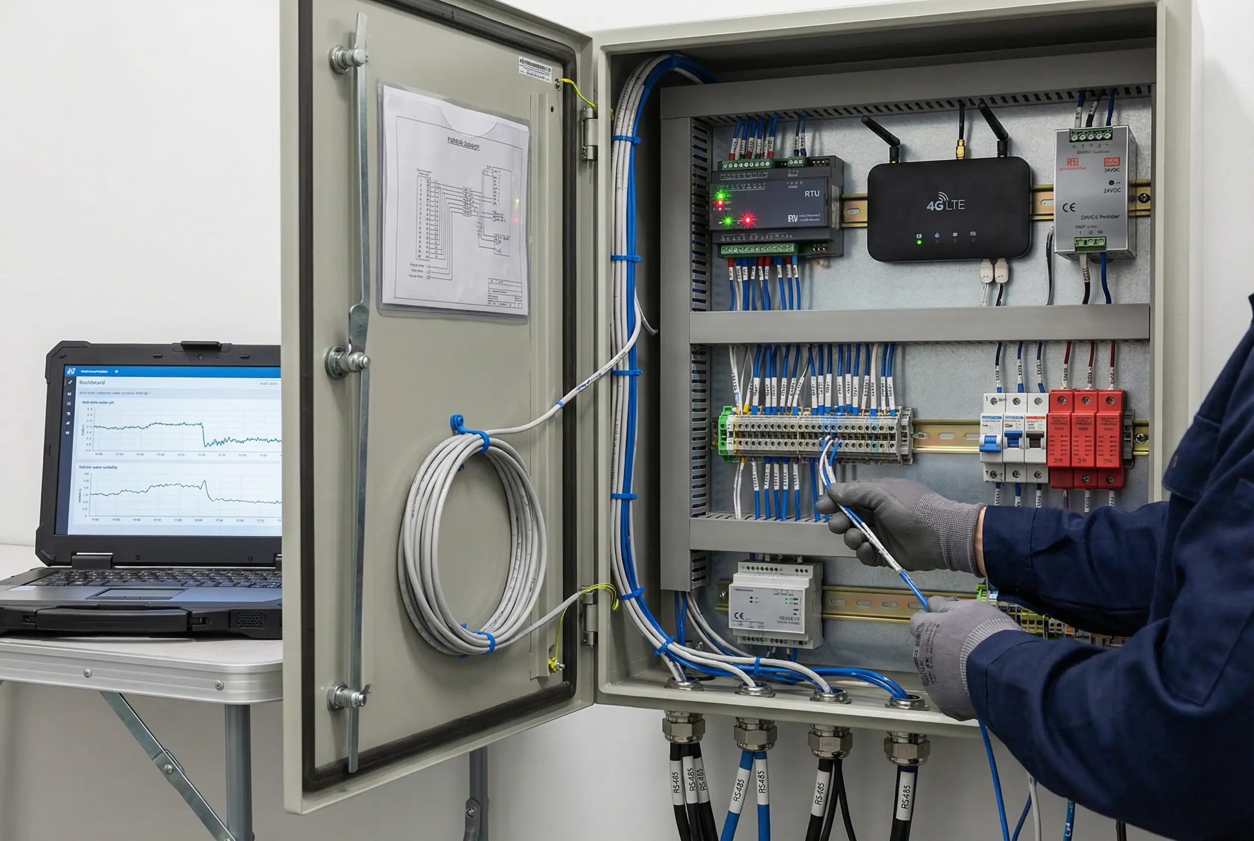
Figure 11.2: Cabinet wiring and commissioning — technician connecting RS485 sensor cables to DIN rail terminal blocks inside weatherproof monitoring cabinet, showing RTU controller, 4G LTE router, 24VDC power supply, surge protection devices, and labeled cable glands; laptop on adjacent table displaying live water quality monitoring dashboard
11.3 Installation Sequence and Requirements
The installation must follow a defined sequence to ensure safety and correct system operation. Civil works must be completed and cured before mechanical installation begins. All electrical work must be completed before power is applied. Sensor calibration must be performed before the system is connected to the cloud platform.
| Phase | Step | Activity | Key Requirement | Verification |
|---|---|---|---|---|
| 1. Civil Works | 1.1 | Site survey and marking | Confirm flood level, access, and cable route | Site survey report signed by engineer |
| 1.2 | Foundation construction | Concrete pier or steel post foundation per structural design | Concrete strength test certificate (28-day cure) | |
| 1.3 | Cable conduit installation | HDPE conduit from sensor location to cabinet; minimum 50 mm ID | Conduit continuity test; end caps installed | |
| 2. Mechanical | 2.1 | Cabinet pole installation | Galvanized steel pole, plumb within 1 degree, anchor bolts torqued to spec | Plumb check; torque wrench record |
| 2.2 | Cabinet mounting | Cabinet mounted at 1.5 m height; door opens away from prevailing wind | Height measurement; door operation check | |
| 2.3 | Sensor bracket mounting | SS316L bracket bolted to pier; sensor deployment depth per design | Depth measurement; bracket torque record | |
| 3. Electrical | 3.1 | DIN rail component installation | Install RTU, gateway, power supply, SPDs, breakers per layout drawing | Component positions match layout drawing |
| 3.2 | Cable pulling and termination | Pull RS485 cables through conduit; terminate at terminal blocks; label all cables | Insulation resistance test; continuity test; label check | |
| 3.3 | Grounding system installation | Ground rod driven to minimum 1.5 m depth; ground resistance less than 4 ohm | Ground resistance measurement certificate | |
| 3.4 | Power-on sequence | Apply power in sequence: main breaker, DC supply, RTU, gateway, sensors | Voltage measurements at each stage; no fault indicators | |
| 4. Commissioning | 4.1 | Sensor calibration | Calibrate all sensors with NIST-traceable standards; record results | Calibration certificates; within-tolerance verification |
| 4.2 | RTU configuration | Configure Modbus addresses, polling intervals, alarm thresholds | Configuration file backup; live data verification | |
| 4.3 | Cloud connectivity test | Verify data transmission to cloud platform; confirm all parameters received | Cloud dashboard showing all parameters; 1-hour data log review |
11.4 Common Installation Errors and Prevention
Field experience from hundreds of monitoring station installations has identified a set of recurring errors that cause system failures, data quality problems, or premature hardware failure. The table below summarizes the most common installation errors, their consequences, and the preventive measures that must be applied during installation.
| Error Category | Common Error | Consequence | Prevention |
|---|---|---|---|
| Electrical | RS485 bus without termination resistors | Communication errors, data corruption, intermittent failures | Always install 120-ohm termination resistors at both ends of the RS485 bus |
| Electrical | Incorrect Modbus address (duplicate addresses) | Sensors fail to respond; wrong data attributed to wrong sensor | Assign unique Modbus addresses before installation; document in register map |
| Mechanical | Sensor deployed too close to bank or bottom | Turbidity and sediment interference; sensor damage during floods | Deploy sensor minimum 0.3 m from bank and 0.5 m from bottom; verify depth |
| Sealing | Cable glands not fully tightened | Water ingress into cabinet; corrosion and short circuits | Torque all cable glands to manufacturer specification; test with IP68 spray test |
| Grounding | Ground resistance exceeds 4 ohm | Inadequate lightning protection; equipment damage from surge events | Measure ground resistance before energization; add ground rods if needed |
| Solar | Solar panel shaded by vegetation or structure | Insufficient charging; battery depletion; system shutdown | Conduct shading analysis at winter solstice sun angle; clear vegetation 3 m radius |