Chapter 7 — Support and Integration
This chapter describes the supporting systems and integration requirements that enable a surface water monitoring station to operate reliably, communicate with external platforms, and be maintained efficiently over its operational lifetime. It covers power support systems, communications infrastructure, calibration support, physical security, and integration with SCADA, regulatory, and GIS platforms.
7.1 Integrated Supporting Equipment Overview
A complete monitoring station requires eight categories of supporting equipment beyond the core measurement instruments. These supporting systems collectively ensure uninterrupted power, physical security, reliable communications, accurate calibration, and safe field operations. The diagram below shows all eight supporting equipment categories and their integration with the central monitoring station.
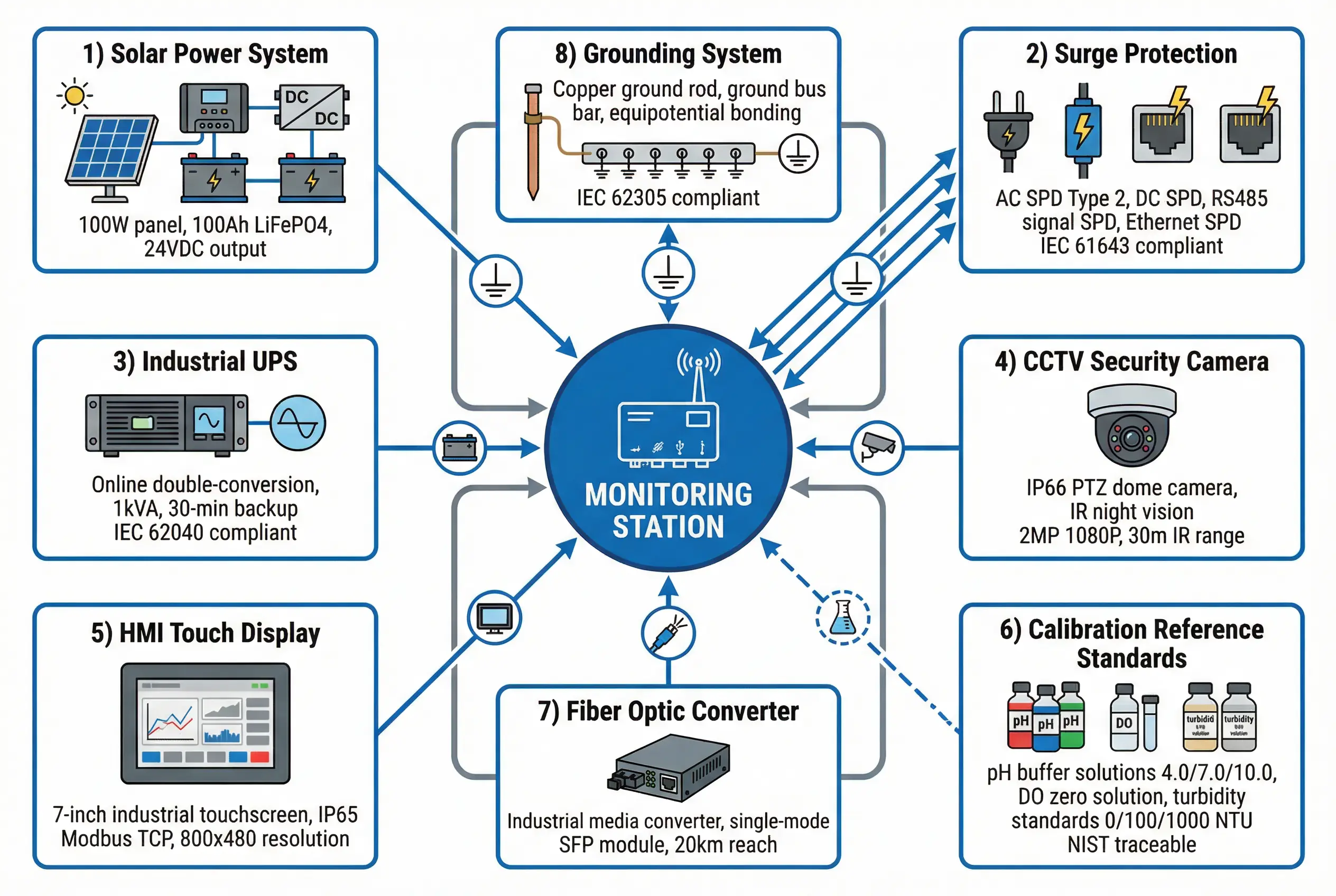
Figure 7.1: Integrated supporting equipment diagram — all eight supporting system categories shown in a hub-and-spoke layout with the monitoring station at center, including solar power, surge protection, UPS, CCTV, HMI display, calibration standards, fiber optic converter, and grounding system
7.2 Power Support Systems
The power support system must provide uninterrupted 24 VDC supply to all station equipment under all foreseeable conditions, including grid outages, cloudy weather, and battery aging. The design must account for the worst-case power consumption of all connected equipment, the worst-case solar irradiance at the site, and the required autonomy period without solar charging.
| Power Component | Specification | Sizing Basis | Key Selection Criteria |
|---|---|---|---|
| Solar Panel | Monocrystalline, 100-200 W, 12/24 V | Daily energy demand / peak sun hours at site latitude | Temperature coefficient, wind load rating, anti-PID coating |
| MPPT Charge Controller | 12/24/48 V auto, 20-40 A, MPPT efficiency greater than 98% | Panel short-circuit current x 1.25 safety factor | Load control output, battery type compatibility (LiFePO4/AGM), remote monitoring |
| Battery Bank | LiFePO4 preferred; 50-200 Ah at 24 V | Daily energy demand x autonomy days / DOD (0.8 for LiFePO4) | Cycle life (greater than 2000 cycles), BMS protection, operating temperature range |
| Industrial UPS | Online double-conversion, 500 VA to 2 kVA, 24 VDC input | Total equipment load x 1.3 safety factor | Input voltage range, bypass mode, remote monitoring via SNMP |
| AC/DC Power Supply | DIN-rail, 24 VDC output, 5-20 A, 85-265 VAC input | Total 24 VDC load x 1.2 safety factor | MTBF greater than 500,000 h, operating temperature -40 to +70 degrees C, CE/UL certified |
7.3 Platform Integration Requirements
Surface water monitoring data must typically be integrated with multiple external platforms, including regulatory reporting systems, SCADA/DCS platforms, GIS mapping systems, and third-party data portals. Each integration has specific protocol, data format, and security requirements that must be addressed in the system design. The table below summarizes the integration requirements for the most common external platform types.
| External Platform | Integration Protocol | Data Format | Reporting Frequency | Authentication | Key Requirement |
|---|---|---|---|---|---|
| Regulatory reporting system (e.g., EPA, MEE) | REST API / FTP / custom XML | XML (HydroML, WaterML) or CSV | Hourly or daily averages | API key + TLS | Data must pass QA/QC before submission; audit trail required |
| SCADA / DCS | Modbus TCP, OPC-UA, DNP3 | Register map / tag values | Real-time (1-60 s) | VPN + firewall rules | Latency less than 5 s; alarm integration required |
| GIS / mapping platform | REST API (GeoJSON, WFS) | GeoJSON, KML, WMS | Hourly or on-demand | OAuth 2.0 / API key | Station coordinates must be in WGS84; time zone must be specified |
| Public data portal | REST API (JSON) | JSON (ISO 8601 timestamps) | 15-min or hourly | API key | Data must be anonymized if required; rate limiting must be respected |
| Early warning system | MQTT / WebSocket / SMS gateway | JSON alarm payload | Event-triggered (real-time) | TLS + token | Alarm delivery latency less than 30 s; acknowledgment required |
7.4 Calibration Support Requirements
Calibration support encompasses the reference standards, equipment, procedures, and documentation required to maintain sensor accuracy throughout the operational life of the monitoring system. A structured calibration program is essential for regulatory compliance and for maintaining the defensibility of the monitoring data. The calibration program must specify the calibration interval for each parameter, the reference standards to be used, the acceptance criteria, and the corrective actions to be taken when calibration fails.
| Parameter | Calibration Method | Reference Standards | Recommended Interval | Acceptance Criteria |
|---|---|---|---|---|
| pH | 2-point or 3-point buffer calibration | pH 4.00, 7.00, 10.00 NIST-traceable buffers | Monthly (or after cleaning) | Slope 95-105%; offset within 30 mV of theoretical |
| Dissolved Oxygen | Air-saturated water or sodium sulfite zero | Barometric pressure + temperature for saturation value | Monthly | Within 0.2 mg/L of reference at saturation |
| Turbidity | Multi-point with formazin or AMCO-AEPA standards | 0, 100, 1000 NTU NIST-traceable standards | Quarterly (or after cleaning) | Within 5% of standard value at each point |
| Conductivity / EC | Single-point with certified standard solution | 1413 uS/cm or 12.88 mS/cm NIST-traceable | Monthly | Within 2% of standard value |
| Water Level | Field verification against staff gauge or surveyed benchmark | Surveyed benchmark (NAVD88 or local datum) | Quarterly | Within 1 cm of benchmark reading |