Chapter 5 — Selection & Interfaces
This chapter provides detailed selection criteria, interface specifications, and a core product function table for the primary instruments and components used in surface water monitoring systems. It covers multi-parameter probes, turbidity sensors, data loggers, communications equipment, and supporting hardware, with guidance on matching product specifications to site requirements.
5.1 Core Product Introduction
The six core product categories shown below represent the essential hardware required for a standard surface water monitoring station. Each product category has specific selection criteria that must be matched to the site conditions, monitoring objectives, and integration requirements. The photograph below illustrates representative products from each category.
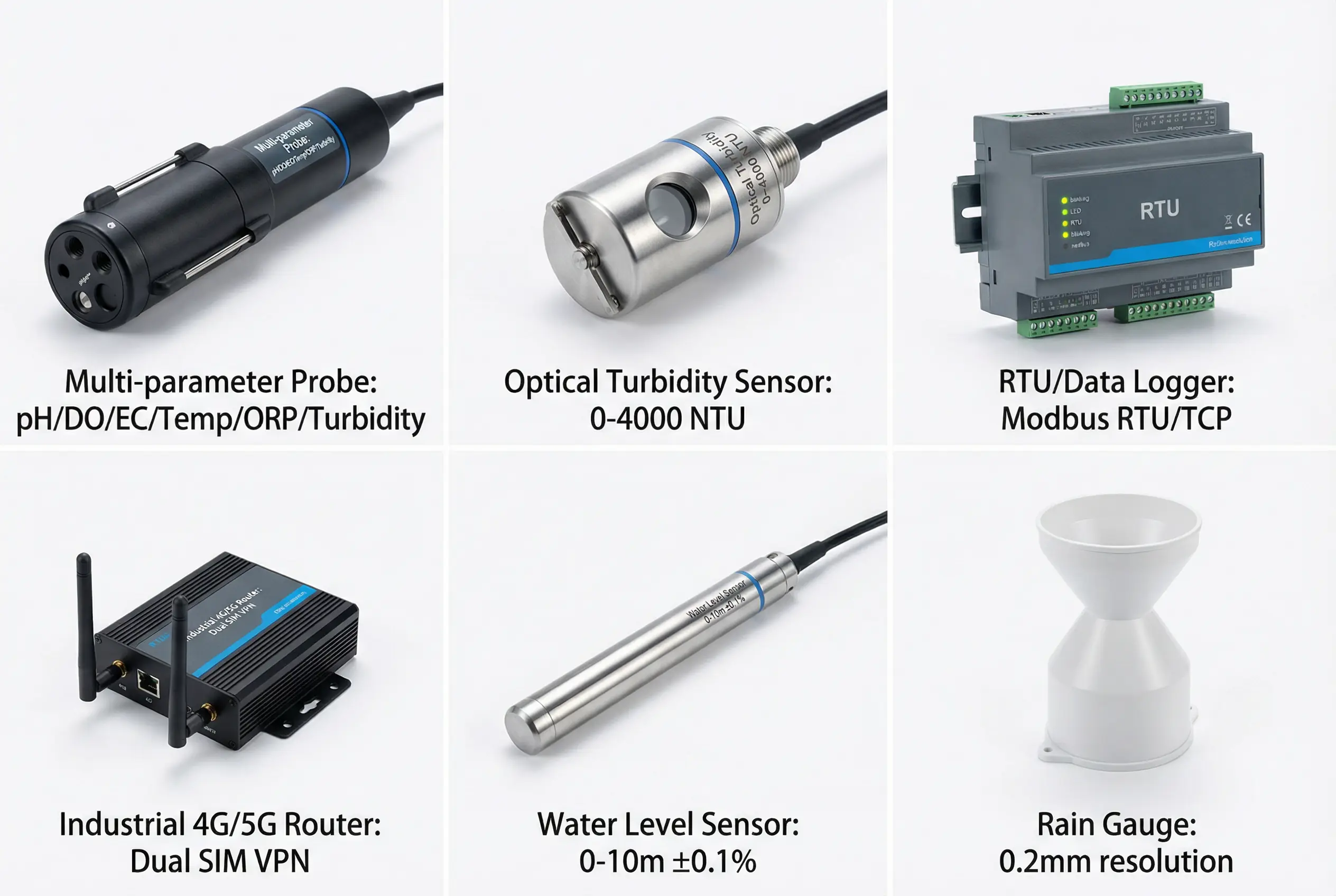
Figure 5.1: Core product showcase — six essential instrument categories for surface water monitoring: multi-parameter probe, turbidity sensor, RTU/data logger, industrial 4G/5G router, water level sensor, and rain gauge
5.2 Core Product Function Table
The table below provides a comprehensive comparison of core product specifications, selection criteria, and interface requirements across all six product categories. This table serves as the primary reference for procurement engineers and system integrators.
| Product Category | Key Parameters | Measurement Range | Accuracy | Interface | IP Rating | Key Selection Criteria |
|---|---|---|---|---|---|---|
| Multi-parameter Probe | pH, DO, EC, Temp, ORP, Turbidity | pH: 0–14; DO: 0–20 mg/L; EC: 0–200 mS/cm; Temp: -5 to +70 °C | pH ±0.1; DO ±0.1 mg/L; EC ±1%; Temp ±0.1 °C | RS485 Modbus RTU; SDI-12 | IP68 (50 m) | Wiper type; anti-biofouling coating; calibration interval; sensor material compatibility with water chemistry |
| Turbidity Sensor | Turbidity (NTU); optional TSS proxy | 0–4000 NTU (auto-range) | ±2% FS or ±0.5 NTU (whichever greater) | RS485 Modbus; 4–20 mA | IP68 | Optical wiper; 90° scatter vs. forward scatter; anti-fouling window material; range switching |
| RTU / Data Logger | Data acquisition, control, local storage | 4–8 RS485 ports; 4–8 AI; 8–16 DI/DO | ADC 16-bit; timing ±1 s (NTP synced) | RS485, RS232, Ethernet, USB, CAN | IP30 (cabinet); IP65 (standalone) | Watchdog timer; local flash storage ≥ 8 GB; operating temp -40 to +70 °C; CE/FCC certified |
| Industrial 4G/5G Router | Cellular uplink; VPN; dual SIM | 4G LTE Cat4/Cat12; 5G Sub-6GHz | N/A (communications device) | Ethernet WAN/LAN; RS232/485 serial; USB | IP30 (cabinet) | Dual SIM failover; VPN (OpenVPN/IPsec); watchdog; operating temp -40 to +70 °C; MTBF ≥ 100,000 h |
| Water Level Sensor | Hydrostatic pressure → water level | 0–10 m; 0–30 m (site dependent) | ±0.1% FS (±1 cm at 10 m range) | RS485 Modbus; 4–20 mA; SDI-12 | IP68 (100 m) | Vented vs. non-vented cable; titanium/SS316L body for corrosive water; lightning protection on cable |
| Tipping Bucket Rain Gauge | Rainfall accumulation | 0–999.9 mm (no upper limit) | ±2% at ≤ 2 mm/min; ±3% at ≤ 4 mm/min | Pulse output (reed switch); RS485 optional | IP54 | Orifice diameter 200 mm; debris screen; self-emptying; heated version for freezing climates |
| Algae Sensor (Optional) | Chlorophyll-a; Phycocyanin (cyanobacteria) | Chl-a: 0–500 µg/L; PC: 0–200,000 cells/mL equiv. | ±5% FS; detection limit 0.1 µg/L Chl-a | RS485 Modbus; SDI-12 | IP68 | Optical wiper; sunlight rejection; temperature compensation; anti-fouling coating |
| Auto-Sampler (Optional) | Triggered grab sampling for lab analysis | 24 bottles × 1 L; or 4 bottles × 3 L | Sample volume ±5%; timing ±1 min | Digital trigger input; RS485 Modbus | IP54 (cabinet) | Refrigerated (0–4 °C) for chain-of-custody; peristaltic pump; sample log with timestamp; lockable |
5.3 Typical Interface Wiring and Connection Logic
The interface diagram below illustrates the complete connection logic between the RTU/PLC unit and all peripheral devices, including sensors, communications equipment, power supply, and output channels. The diagram uses color-coded wiring to distinguish power, signal, and communications circuits, and shows connector pinouts for the most common interface types used in surface water monitoring applications.
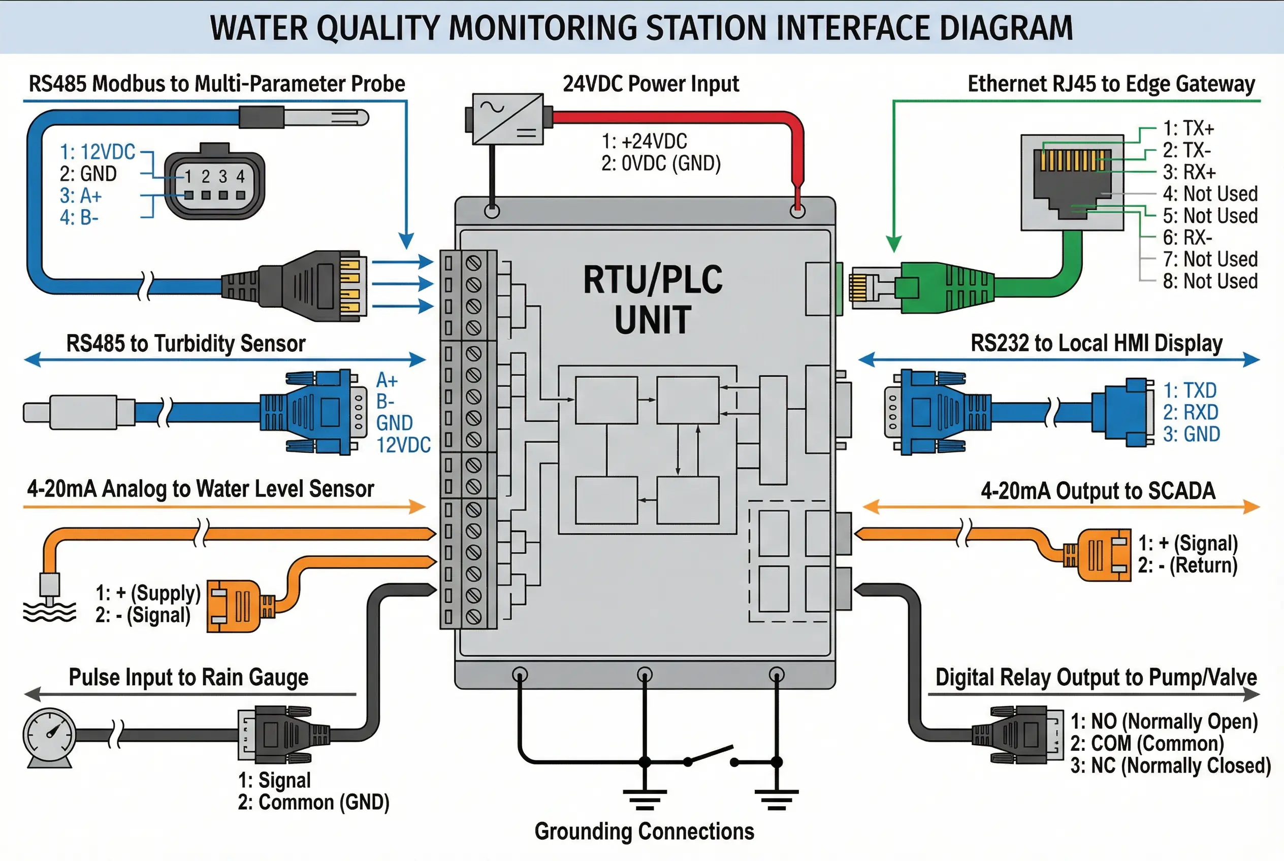
Figure 5.2: Interface wiring and connection logic — RTU/PLC central unit with labeled connections to all sensors, communications equipment, and output channels, showing connector pinouts and color-coded wiring
5.4 Interface Compatibility Requirements
Interface compatibility between components is a critical design requirement that is frequently overlooked during procurement. The table below summarizes the key compatibility requirements and common incompatibility risks for each interface type used in surface water monitoring systems.
| Interface Type | Standard | Max Cable Length | Max Devices on Bus | Common Incompatibility Risk | Mitigation |
|---|---|---|---|---|---|
| RS485 Modbus RTU | EIA-485; Modbus RTU | 1200 m (120 Ω termination) | 32 (standard); 256 (with repeater) | Address conflicts; baud rate mismatch; missing termination resistor | Unique address per device; match baud rate; 120 Ω at both ends |
| 4–20 mA Analog | IEC 60381-1 | 300 m (loop resistance limited) | 1 (point-to-point) | Ground loops; loop resistance too high; ADC input range mismatch | Single-point grounding; verify loop resistance; match ADC range |
| SDI-12 | SDI-12 v1.3 | 60 m | 62 (addresses 0–9, A–Z, a–z) | Address conflicts; timing violations; power supply noise | Unique SDI-12 address; shielded cable; stable 12 VDC supply |
| Ethernet (Modbus TCP) | IEEE 802.3; Modbus TCP | 100 m (Cat5e/6) | Unlimited (switched network) | IP address conflicts; firewall blocking port 502; network loop | Static IP assignment; open port 502; managed switch with STP |
| Pulse (Rain Gauge) | Reed switch; open collector | 200 m | 1 per DI channel | Debounce not configured; cable capacitance causes missed pulses | Configure 20–50 ms debounce; use shielded cable; test at max rain rate |